

802.11ah: WiFi HaLow
Long range, lower speed, higher capacity IEEE standards-compliant sub-gigahertz WiFi

WiFi Halow (802.11ah) is part of the alphabet soup which is WiFi, and operates in the sub-gigahertz frequency range. WiFi HaLow was approved in 2016, and rolled into the combined IEEE Std 802.11™️‐2020 document1. WiFi HaLow is targeted at the IoT market, supporting long range and low power operation.
Operating in the sub-gigahertz region presents many challenges, including fragmented worldwide unlicensed frequency bands, competing licensed technologies in the same spectrum region, other unlicensed users on the same bands, as well fundamental characteristics of the lower frequency and longer range operation. The HaLow standard attempts to overcome some of these challenges through extension of the core WiFi standards as well as through changes to the PHY layer.
In this article we’ll take a look at some of the new features introduced with HaLow, and some of the differences between it and the better known and more mature of the IEEE 802.11 standards. I’ll be mainly focussing on the MAC layer, dipping my toes into the PHY layer for one new feature.
HaLow features
Although HaLow is built upon the previous WiFi work, some new concepts were introduced to solve the challenges needed for low power and long range devices, for which legacy WiFi is not the optimal solution.
We’ll dive into the following features, which were introduced in the HaLow version of the standard:
PV1 frames;
NDP CMAC frames;
The S1G beacon frame;
Relay operation;
AID and TIM changes;
Restricted Access Window; and
Target Wake Time.
Protocol Version 1 (PV1) frames
If you’re familiar with WiFi, you’ll know about the framing, and about the Frame Control field (section 9.2.4.1) which is present in nearly all MAC frames. Within the Frame Control field there is a 2-bit field ‘Protocol Version’ which was set at the value ‘0’ until HaLow was introduced. The Protocol Version field can now also support the value ‘1’ - to indicate Protocol Value 1 (PV1) frames. Protocol Version 1 was defined as the changes in the MAC header introduced for PV1 are not backwards compatible, as we will see further down.
The PV1 frame types and subtypes currently defined as of the 2020 version of the standard are shown in the following table. From this we can see PV1 frames have two distinct types: Totally new frame types (anything in section 9.8.X), and redefinition of PV0 frames (Action and Action No ACK) to make use of the more efficient MAC headers which are supported by PV1.

The advantage of using PV1 frames is the reduction in MAC header overhead. As per the frame format diagram in figure 9-978 (section 9.8.2), MAC addresses can be either 6 or 2 bytes long. The 2-byte long MAC address format is named the Short ID (SID), and is outlined in figure 9-980.
Given every PV1 frame must have at least 2 addresses (A1, A2), the saving from using SID rather than full MAC address is 8 bytes maximum, 4 bytes in the case of mixed MAC and SID addresses. Although not a huge saving, consider a sensor application where every microwatt of power is critical and the data size may be very small (a handful of bytes), and the overhead for the transmission will be reduced significantly.
If we compare a PV0 QoS data vs a PV1 QoS data frame with a data payload size of 4 bytes, we have a frame which looks like the following diagram:

This clearly shows us the savings achieved by compressing the MAC header for small data payload sizes. In this case the saving as a percentage is 44%.
If we look at larger data payloads we can plot the header saving percentage PV1 vs. PV0:

As we can see, there is a diminishing benefit as the data size increases, but there is always a benefit, however small.
An S1G station indicates support for PV1 frames when bit 71 in the S1G Capabilities Information field is set to 1 (section 9.4.2.200.2).
NDP CMAC frames
An interesting addition with the 802.11ah standard was the extension of Null Data PPDU (NDP) formats, called Null Data PPDU Carrying Medium Access Control information (NDP CMAC).
NDP CMAC is a cross-layer optimisation where certain frames insert MAC level information into the PHY header, within the SIG field of the PPDU header.
As with PV1 frames, one of the reasons for this optimisation is to reduce the overhead on commonly used frames to save both power and airtime. By overloading the PPDU SIG field, NDP CMAC frames allow information such as duration, RA (partial AID), sequence numbering/bitmaps and other frame specific information to be contained in the PPDU header. By inserting the critical information in the SIG field of the PPDU header, the data portion of the transmission can be omitted, thus leading to airtime and power saving.
Table 23-29 outlines the different NDP CMAC frames which are defined in 802.11ah, and is transcribed below. The mapping from NDP CMAC to an equivalent non-NDP CMAC MPDU is shown.

The format of the SIG field for NDP frames has two variants, one for 1MHz NDPs, the other for ≥2MHz NDPs. These two variants are describe in figure 23-20 and 23-21. The diagram below shows the encapsulation of an NDP BlockAck frame at 2MHz (detail in section 23.3.12.2.6.2). There is an equivalent 1MHz NDP BlockAck in section 23.3.12.2.6.1. The numbers on the second and third layers (the SIG field format and the NDP BlockAck 2MHz frame) are bit offsets.

For further details of NDP CMAC, see section 23.3.12 of the 2020 standard.
S1G beacon
One of the critical frames in ensuring an operational and effective WiFi network is the beacon frame. The beacon frame contains a lot of information relevant to the operation of the given BSS or BSSes (see table 9-32 for the list of the fields and IEs which can be present), and has a fairly significant overhead, even on high speed (2.4/5/6GHz) networks. In busy areas with tens to hundreds of APs simultaneously running, the overall airtime consumed by beacons can be significant, and when translating this to the low data rates in S1G, the overhead can quickly leave no room for useful data transmissions.
HaLow made a couple of changes to beaconing, again, to assist with airtime usage and ensure efficient control information broadcast. The first of the changes was to overhaul the format of the beacon frame (section 9.3.4.3) and to remove redundant address fields and make other fields optional. The S1G beacon is an extension frame, that is, in the Frame Control field the type value is ‘3‘, with subtype ‘1‘. The second of the changes specific to HaLow was to introduce the concept of ‘short beacons’.
Short beacons when compared to full beacons do not contain all of the field and information elements which are present in the full beacon. As a general rule, the majority of fields and IEs in beacons are rarely updated, so it makes sense to exclude them to save airtime. HaLow introduces a Change Sequence field (a 1-byte field in the beacon header) which is present in both full and short beacons. The Change Sequence field notifies clients when fields or IEs are updated, which gives them opportunity to re-parse the beacon contents.
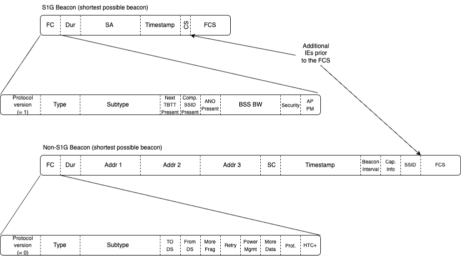
Table 9-46 shows the fields and IEs which may be present in both the short and full beacon. Optimisations for S1G beacons are made through removal of the full TSF counter in every beacon. The timestamp field reduces from 8 to 4 bytes (which contain the lower bytes of the full 64-bit TSF counter), with the upper bytes of the TSF present in the S1G Beacon Compatibility element (section 9.4.2.196). The relationship between the short beacon and the full beacon is communicated to clients through the Short Beacon Interval IE (section 9.4.2.197).
The diagram below gives a comparison of the S1G beacon header vs. non-S1G beacon header. Again, we see the size optimisation designed into the protocol, which in turn leads to airtime and power optimisation. Note that the Frame Control field in the S1G beacon has a different format, allowing further space optimisations in the beacon via the Compressed SSID Present, Next TBTT Present and ANO Present bits, which indicate whether optional fixed fields are present in the beacon frame header. This diagram shows the shortest beacon frames possible. Note how the S1G shortest beacon (a typical short beacon) is more than 50% shorter than the shortest possible non-S1G beacon. Also note that non-S1G beacons generally have 100-300+ bytes of additional IEs present. ie, this is a bit of an apples to oranges comparison, the true relative saving S1G : non-S1G beacon would be many times higher.
A final note on S1G beacons is that the short beacon concept looks remarkably similar to a patent which I filed with Cisco in the early 2000s, which can be found here. This patent is still current, I wonder if the IEEE know about it?
Relay operation
The S1G Relay functionality provides a very basic mesh-type networking implementation, which extends the reach of devices which may not be able to directly connect to the root AP. This is done through use of a relay function, which operates in S1G Relay capable devices. A typical use-case for S1G Relay would be in long range networks, where device density is low and distances are long. The cost of deployment of root APs may be very high in these situations, and the use of relay can extend the effective range of the network significantly. This type of relay network is only suitable for low bandwidth applications as the overhead can be high for deep tree networks with multiple relays.
S1G Relay is outlined in section 10.54 of the standard. An example relay network is shown in the following figure (a rework of figure 10-112 in the standard).

The concepts in an S1G relay network are:
S1G Relay AP - the function into which non-relay STAs or S1G Relay STAs connect. Any S1G device which is relay capable has an S1G Relay AP function.
S1G Relay STA - the function which connects to either an S1G Relay AP or the Root AP. Any S1G device which is relay capable has an S1G Relay STA function.
Relay Function - the function within the S1G relay device which forwards frames from the devices connected to the S1G Relay AP.
Reachable Address updates - an update frame to inform the higher layers in the relay tree how to reach a given device via its MAC address.
Root AP - the regular AP, which deals with frame forwarding within the S1G relay network. This device has full visibility into the relay network topology and all MAC addresses present.
S1G non-relay STA - this is a regular STA, or leaf node in the network.
In the example topology shown, all of the devices named ‘Relay’ have both an S1G Relay STA and an S1G Relay AP running within them. STAs connect into S1G Relay APs or Root APs. S1G Relay STAs connect into S1G Relay APs or Root APs (ie, enabling the Relay Function).
The establishment of the Relay Function is via the S1G Relay Activation element within the (re)association request/response (section 9.4.2.206), or through use of the Relay Activation Request and response action frames (sections 9.6.25.3/4).
The ability for an S1G device to act as a relay is determined through the S1G Relay element (section 9.4.2.204) which is included in beacon and probe response frames. This element can indicate the role that the device plays within the overall relay network - either a parent (root) AP or an S1G relay AP.
When a relay link is established between two relay capable nodes using the S1G Relay Activation element, the Reachable Address element (section 9.4.2.205) within the Reachable Address Update action frame (section 9.6.25.2) is used to indicate which devices are reachable from the given S1G relay STA. This informs the Root AP as to the connectivity of the entire relay network, and enables correct packet forwarding.
Data transfer within the relay network is achieved through either 4-address frames or through A-MSDU frames. Four address frames are essential to ensure the ultimate source of the transmission is not lost. Using A-MSDU avoids address loss as the individual MSDUs within the A-MSDU contain the required information (ultimate source and ultimate destination MAC addresses).
Maximum Association ID (AID) and TIM IE
As mentioned earlier in the article, given the large range increase given by operating in sub-gigahertz frequencies, the individual BSS cell size serviced by a single AP increases. The base 802.11 standard allow up to 2007 STAs to connect into a single AP, each with unique Association ID (AID). Although in practice this limit is never reached - I have heard of devices that can support up to 1000 nodes simultaneously - when the potential BSS size increases by a factor of 1000, the 2007 AID limit becomes inadequate, especially when considering IoT applications where there may be hundreds to thousands of sensors per BSS.
With this in mind, HaLow increased the AID space from 2007 to 8191 devices, approximately a 4-fold increase. The AID assigned when a HaLow client is connecting (via the association response frame) is communicated through a new IE, the AID Response element (section 9.4.2.194). This element can also be used to force stations to change their AID, a very useful feature to group AIDs and reduce the overhead of power save operations via the TIM IE.
When considering an AID size of 8,000+ devices, problems occur when communicating power save state using the regular TIM IE. Consider that the virtual bitmap inside the TIM IE is up to 251 bytes long. With 8 bits per byte, the TIM can notify a maximum of 251 x 8 = 2008 STAs, way below the maximum AID count supported in HaLow. Fortunately the clever people who wrote the standard considered this, and introduced several new modes for TIM operation!
Section 9.4.2.5 and its subsections outline the various TIM operational modes, one of interest for the new AID count being Page Slicing. Page Slicing is detailed in section 10.51, and is a method to allow different parts of the TIM virtual bitmap to be communicated to groups of clients across different beacons. Think of Page Slicing like a window into the entire AID space, one which is communicated progressively as beacons are transmitted.
With HaLow, the AID space is divided into pages, pages are divided into blocks, and blocks divided into sub-blocks (see figure 9-152) to allow different views into the window of AIDs. Different modes are supported with Page Slicing, which are outlined in sections 9.4.2.5.2 to 9.4.2.5.5. These modes offer significant flexibility in which parts of the AID space are communicated in the TIM partial virtual bitmap field, allowing significant room for vendors to differentiate when it comes to power save operation.
One final note about the increase in the maximum AID and very large device count networks is that a new feature, Centralized Authentication Control (CAC) was introduced with HaLow in an attempt to solve the ‘power reset reconnection’ problem of thousands of devices simultaneously authenticating with the root AP in the case of a power outage or restart of the root AP. This feature is defined in section 11.3.9, but it is unclear whether it offers any real-world benefit.
Restricted Access Window (RAW)
With the explosion in the number of possible devices in a HaLow BSS, and the vastly reduced bandwidth available for these devices, medium contention becomes a huge challenge.
To help HaLow applications overcome some of the contention issues, a new feature was introduced: Restricted Access Window (RAW). The idea behind RAW is to divide stations into groups, and assign each group a time slot during which they are allowed to transmit. During a given RAW time slot, only the devices which are part of the group associated with the RAW time slot may contend for the medium and transmit.
The upshot of enabling RAW mode has been shown through simulation to increase aggregate throughput by up to 300%2, however, it is still unclear whether this translates to real-world benefits.
Restricted Access Window operation is defined in section 10.23.5 of the standard. Support for RAW operation is indicated in the S1G Capabilities element, using bit 51 (defined in section 9.4.2.200). Indication of RAW grouping and slots is achieved through the use of the RPS element (section 9.4.2.191), which is included in the S1G beacon, both the short and non-short variants.
The RPS element configures various parameters associated with the RAW period, including the definition of the time slot, the start time of the RAW period, which group of AIDs is associated with the RAW period, the maximum channel bandwidth to be used, whether uplink, downlink or both are to be used during the RAW period, and whether the RAW period repeats (periodic RAW or PRAW) or single shot.
When an STA receives an RPS element which indicates a RAW period, if the STA AID is within the RAW Group subfield AID range, then the STA can participate in that RAW period. If the STA receives the RPS element and the STAs AID is not part of the Raw Group subfield AID range, then that STA may not participate in the RAW period - ie, the STA remains silent for the full duration of the period.
The STAs within the group indicated by the Raw Group subfield will contend for access for transmission during the RAW period, not earlier than the slot assigned to their AID. The slot is calculated based on the AID of the STA plus an offset (the two least significant octets of the beacon FCS containing the RPS element), modulo the number of slots within the RAW period. Using the two least significant octets of the beacon FCS gives some randomness in the slot ordering vs. AID, assuming the beacon frame updates on each transmission, which it will do due to the timestamp field!
Two variants of slot assignment exist: the first being all STAs within the Raw Group being assigned a slot regardless of the AID for the STA being enabled in the TIM bitmap of the preceding beacon. The second variant being only those STAs whose AIDs in the preceding beacon TIM bitmap are set, are assigned a slot. These cases are outlined in figures 10-32 and 10-33 of the standard.
The diagram below shows how a single RAW period is broken up into 5 slots, with the 5 STAs with AID 65→69 participating in the RAW period (see the RPS IE RAW Group field), and a single STA with AID 70 which is not participating in the RAW period. The green boxes in the diagram show when an STA is allowed to contend for the medium. The red boxes in the diagram show when an STA is not allowed to contend for the medium.

The calculation of which STA starts contending in which slot position is done with the equation:
Where:
x is the AID of the STA (65 → 69)
N(offset) is the offset value (the least significant two bytes of the beacon FCS, 0x0003)
N(RAW) is the number of slots in the RAW period (5)
Substituting the values in the RAW diagram we get the following slot mapping:
STA 1 AID: 65 → slot 3
STA 2 AID: 66 → slot 4
STA 3 AID: 67 → slot 0
STA 4 AID: 68 → slot 1
STA 5 AID: 69 → slot 2
As you can see from the diagram, the slot times are used to effectively slowly introduce STAs into the restricted contention period, theoretically reducing the likelihood that collisions and lost airtime will occur. Note also that the EDCA backoff within the RAW period is different than during non-RAW periods. See section 10.23.5.5 for full details.
We’ve only skimmed the surface of RAW, if you want more details then dive into the standard in the sections I’ve mentioned.
As for use-cases of RAW other than trying to reduce contention in large HaLow networks, the big one is real-time video streaming such as from security cameras. The traffic profile of real-time streaming video devices can align nicely with the ability of RAW to deliver better than best effort upstream bandwidth. Ultimately the use of RAW to reduce contention is another power conservation feature, one which hopes to prevent collisions, which in turn consume power through retransmissions.
What other use-cases do you think RAW can effectively apply to? Join the WiFi Diving chat and we can talk!
Target Wake Time (TWT)
The major use-case of HaLow is to support ultra low-power devices. Low power enabled IoT applications are devices which may be powered for years at a time on a single small battery, or eternally powered through solar power plus battery.
To support ultra low-power operation and long battery life, the device must reduce both transmit and receive to a minimum, and spend log periods of time in the lowest possible power states. One feature which was introduced by HaLow (and adapted + extended in 802.11ax) is Target Wake Time (TWT). Target Wake Time is defined in section 10.47 of the standard.
In addition to allowing low power modes, TWT can assist in reducing congestion through clever scheduling of device sleep/wake periods.
Target Wait Time is a mechanism which allows STAs and APs to negotiate periods when the station will be awake and can transmit and receive. Each STA can establish up to 8 independent TWT Agreements, and they can be implicit (automatically renew based on the TWT parameters), or explicit (renegotiated at the end of each Service Period).
TWTs are defined by a wake interval, and a Service Period (SP), and are negotiated using action frames to form a TWT Agreement.
A simplified diagram showing how TWT can reduce power consumption is below. In this diagram the green sections represent when the client is in high power mode (receiving), yellow sections represent when the client is in low power mode. In legacy operation, beacon 1, 3 and 4 indicate group addressed frames are buffered, so the client must remain awake for longer periods of time than expected. In TWT operation the client remains asleep for significantly longer periods of time, in this case for two beacon periods, although this period can be extended significantly as we will soon discover.

The TWT Wake Interval, which specifies the sleep time of an STA, can exceed legacy power save mechanisms, and span microseconds, seconds, minutes, hours, days, weeks, months or years. Calculation of the TWT wake interval is based on the TWT Wake Interval Exponent and the TWT Wake Interval Mantissa field in the TWT Request field, both of which are in the TWT element (section 9.4.2.199). The calculation of the TWT sleep interval is:
Substituting the maximum possible values:
TWT Wake Interval Mantissa → 16-bit field, maximum value 65,535
TWT Wake Interval Exponent → 5-bit field, maximum value 31
We see the wake interval maximum number is 136,049,531,551,744µS, or a little under 4 and a half years. Slightly longer than the usual sleep period of a couple of beacon periods!
The TWT Service Period is the time during which the STA is available to transmit and receive - ie, the STA will be awake during the SP. At the end of the SP, the TWT is either automatically reinstalled (implicit TWT) or renegotiated again (explicit TWT).
With such long sleep periods, many problems can crop up such as:
TSF clock drift in the STA vs. AP - periodic wake to re-synchronise the TSF in the beacon is required, thus losing some of the power saving benefits.
AP resource exhaustion - imagine 8,000 STAs establishing 8 x TWT agreements lasting weeks or months, this could be a potential resource DoS.
Re-key timeouts - how to deliver a new key if the STA remains asleep.
The service providers the IoT device is reporting into goes out of business 😀!
Negotiation of TWT Agreements is by action frames, which contain TWT elements (section 9.4.2.199) within the following S1G action frames:
TWT Setup Frame/Protected TWT Setup frame (sections 9.6.24.8, 9.6.25.6)
TWT Teardown Frame/Protected TWT Teardown frame (sections 9.6.24.9, 9.6.25.7)
In addition to the negotiation frames, the TWT Information frame/Protected TWT Information frame (sections 9.6.24.12, 9.6.25.8) can be used to query the state of TWT agreements between peers.
An interesting additional feature within TWT for HaLow is the use of NDP Paging (using the NDP Paging NDP CMAC PPDU format, section 23.3.12.2.8) in order to efficiently determine if there are any buffered MPDUs waiting for the STA participating in the TWT agreement. NDP Paging works by the STA side sending an NDP Paging request, to which the AP responds with an NDP Paging response frame. The advantage of this method is as with other NDP CMAC frames, saving of airtime through population of MAC layer information in the PHY header. The NDP Paging exchanges can indicate whether traffic is buffered for the given STA, and whether there are critical beacon updates which warrant the STA receiving and parsing a new beacon. Recall that TWT allows an STA to be asleep across multiple beacon periods.
We’ve skimmed TWT at a high level here, I highly recommend that you read all of the relevant sections in the standard if you want to become a TWT expert!
Other considerations
In addition to the new features in HaLow which we’ve run through, there are other considerations relating to unlicensed spectrum usage, worldwide unlicensed spectrum inconsistencies and region-specific requirements such as transmission duty cycle restrictions. These issues are not unique to HaLow, are outside of the core standard, and would warrant additional articles to dive deeper.
Conclusion
In this article we’ve looked into some of the unique and interesting features of WiFi HaLow, which is defined in IEEE 802.11ah and is part of the IEEE Std 802.11™️‐2020 version of the standard. WiFi HaLow is designed specifically for Internet of Things devices, and provides additional power saving mechanisms, increased AP capacity, and improved range as compared to the other WiFi standards.
Have you worked with HaLow devices yet? Did you know about HaLow before reading this article? Do you think it’ll succeed or fade into the background like so many other under-utilised but worthy technologies?
Comment below or join the WiFi Diving Substack chat here! Let’s talk!
Please also take a look at the Support WiFi Diving page - feel free to help out by purchasing some of your gear through my Amazon Associates links!
As always, constructive comments are welcome. Please let me know of any inaccuracies or corrections I need to make.
I hope you enjoyed reading and learned something new from this article!

IEEE Standard for Information Technology — Telecommunications and Information Exchange between Systems Local and Metropolitan Area Networks — Specific Requirements.
Part 11: Wireless LAN Medium Access Control (MAC) and Physical Layer (PHY) Specifications (IEEE Std 802.11™️‐2020) - https://ieeexplore.ieee.org/document/9363693
Thank you Richard !
The first time I heard about WiFi HaLow in2018 when I came across a company called Morse Micro. The technology sounds fascinating ! However, any worthwhile technology to succeed, there should be a consumer market along with alignment of other factors like timing, economy, luck, marketing and push by corporations/government etc. Sometimes, corporations can create a market by clever marketing.
I remember, there was lot of action happening on WiMAX a decade and half ago but it did not succeed though.